Sunday, February 12, 2012

An Update

It's been awhile...

...but the vehicle is now complete!

What remains is to finish the control software.  Jake is in the thick of FIRST Robotics season (Team 1717, d'Penguineers), and is working on competition code six days a week, so this phase may take some time.

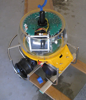
Here are some photos of the final assembly process.  The port hull and viewport were situated vertically,

the camera chassis was inserted via a method most likely to be detailed in the next post,

and the starboard hull was lowered on with a hoist.

Success!

      O
       o
-Jacob˚

Sunday, December 25, 2011

What's Going On Down There (a signal processing adventure)

A safety feature unique to the Hyball ROV and its descendants is vacuum leak detection.  This is a system that allows the operator to draw some air out of the hull before launch, creating a slight vacuum.  A barometric pressure sensor inside the hull lets the operator know if any air or water is leaking back into the vehicle through one or more of its thirty-two O-ring seals.  Ideally, leaks are identified topside, but if a seal fails during a dive, this system acts as the first line of defense for the vehicle and its operators.

Since the original vacuum sensor was missing, I replaced it this, a TDR-120 pressure transducer.

The tricky thing about this sensor is that it produces a differential voltage signal.  Instead of offering one signal terminal whose voltage relative to a 0-volt ground is proportional to the vacuum pressure, it has two terminals at very close positive voltages.  The difference (hence "differential" signal) between these voltages is proportional to vacuum pressure.

I used this little circuit from the LM124 application examples to ground-reference the signal and amplify it so that 0 to -700 torr gauge pressure maps to 0-5V, which can be fed to one of the Arduino's input pins.


It looks slightly different in real life.  The two 714 op-amps are inside the LM324 chip (at bottom):


Rather than narrating the two signal processing operations the circuit performs (ground referencing and amplification), I'll let the simulated oscilloscope and captions do most of the talking:
1) The raw signal coming out of the sensor
(each of the two traces represents a signal pin.)

2) The ground-referenced version of the signal in (1)

3) The signal in (2) amplified for a 5V maximum peak.


The traces above simulate what you'd see while drawing a 700-torr vacuum with the hand pump (below.)
I tested the output scale of the signal processing circuit by connecting it to a voltmeter, hooking the pump hose directly to the sensor, and comparing readings between the meter and the pump's mechanical gauge.

Geek on and happy holidays!

-Jacob

Monday, December 5, 2011

Motors


They save the best for last, eh? Anyway the motors...

They're 12VDC, size 550 Duratrax Starter Motors (they're meant for starting internal-combustion engines in radio-controlled vehicles). 55o is the standard size used in electronic radio-controlled vehicles, so why not use them in a remotely-operated vehicle?

Anyway the motors draw up to 148 amps when stalled, and produce about .55 horsepower (this is roughly equivalent to the power output of the motors that the ROV originally came with-- ~380 watts each. Also, the Duratrax motors were the only ones small enough and with enough power to meet the requirements of our project [hence the outrageous stall current]).

Now, all motors have different face-patterns (the arrangement of the tapped holes in the front of the motor for mounting). To adapt the new face pattern to that machined into the motor housing--with tight tolerance to reduce vibration--I commissioned a quick-turn prototyping machine shop (emachineshop.com) to fabricate adapter plates from ~1/8 inch, 6061-T6 multipurpose aluminum alloy (for strength, weight, and--to some extent--cost).

That's about all there is to the motors (the physical bit at least).

Cheerio~

On Yellow Submarines

The propulsion trilogy will finish up soon with a word from Aidan on the motors, which he did most of the work on.

Thanks to Tamrynn Clegg for the Antipodes shots.

In the meantime, there have been some cool happenings at the Sea Center tangentially related to this project.  On November 11 and 12, the team from OceanGate Inc. made a whistle stop on the wharf with their manned research sub Antipodes.


In terms of technical history, Antipodes has a surprising amount in common with our ROV (notwithstanding that it carries people.)  They are both products of the North Sea oil boom, and both feature approximately the same depth rating, at around 300 meters, along with an unbelievable amount of acrylic.  They're also both yellow.


Yellow is likely the most popular body color for research subs, manned and unmanned alike, due to its high visibility.
Nonetheless, one can't help but wonder:
Which came first, the Beatles album or a yellow vehicle?
Finding the answer to this question took some searching, but as it turns out, none other than Jacques Cousteau painted his organization's new submersible yellow in 1966.  The vehicle, believed to have inspired the title of the Fab Four's 1968 album and  animated film, is shown on display at the Oceanographic Museum in Monaco. 
Yet another way marine science affects us all!
image credit to user 4dmin of imagesearch.blogspot.com


Launch is nigh for our yellow sub. Stay tuned!

- Jacob

Friday, November 11, 2011

Looking for Our Missing Pieces, Pt. 1B: Motor Controllers

Now we've gotten some juice from topside down to the vehicle and converted it to a nice, smooth 12 volts DC.  The next step is throttling the amount that goes to the thruster motors.  The device that takes commands directly from the topside computer and sends them to the ROV's various components, acting as a serial mux/demuxer, is an Arduino microcontroller board (more on this later.)  But the Arduino can only generate low-current 5V logic level signals.  We needed something that would bridge the gap between the delicate logic electronics and the high-power, noisy motors turning the props.

This is where motor controllers come: they take the small signals from the microcontroller and let them control the substantially larger (>12,000x as much power dissipated) flow of power to each motor.

The basic circuit for a DC motor controller with reversing capability is known as an H-bridge.  A simplified version using flip switches instead of MOS field effect transistors is shown below.  
click for circuit diagram key
If you've ever tried hooking up a DC motor to a battery, you'll realize that when switches S1 and S4 are closed, the motor will spin one way, and when S2 and S3 are closed, it'll go the other.  This works great for running a motor in two directions, but there was still the issue of controlling its speed.  To do this, we'd have to change VDD, the voltage supplied to the H-bridge.  This is a bigger deal than it might seem, since our control electronics are digital, that is, they can output a HI ("on," or digital 1) or LO ("off," or digital 0) signal, but nothing in between.  We solved this issue by using a commercially available motor controller that modulates speed using a PWM signal.

First, the actual component: we decided on the Turborix EL110 Electronic Speed Controller (ESC), which is rated at 110A in the forward direction, 40A in reverse, and is designed for use in remote-controlled boats.  Here are a couple zipped onto a temporary bracket in the starboard hull. 

Second, I'll explain the acronym so rudely introduced three sentences back: PWM.

Pulse-Width Modulated signals are by definition binary, which means they have rectangular waveforms, and can also be generated by digital electronics.  The information they carry depends on the amount of time the signal spends in the HI state vs. the LO state.  The percent of the phase spent HI is called the duty cycle.  

Diagram of a PWM wave.  Duty cycle is shown in green, constant phase length in blue.
When used to drive a DC motor, these waves serve to imitate an analog variable voltage signal.  For example, instead of putting out a steady 6V to run at 1/2 speed or 9V for 3/4 speed, the ESC generates 12V 50% or 75% of the time.  The high frequency of the PWM signal (about 2500 Hz) and the motor shaft's angular momentum help eliminate the jerking motion one might expect, but the motor still emits a whine.

You can see this post's subject in action when Jake fires up a motor on the bench:

 
Until Next Phase,_,---,_,---,_,--,_,--,_,-,_,-,_,-,   Jacob


Monday, October 31, 2011

Looking for Our Missing Pieces, Part 1A: Power Supply

I left off far too long ago explaining that the ROV had been converted to a drop camera.  This meant that most of the equipment needed to actually make the propellers spin was missing.
The three main parts of the propulsion system are the power modules, motor controllers, and the thruster motors.  Over this and the following two posts, we’ll outline them one by one with explanations of what they’re for, how they work, and what we came up with to replace them.
Here goes:
The ROV's two power modules take the high voltage from the umbilical tether (240 volts AC), and convert it to a safe supply that can be used by the motors (12 volts DC).
Why does the tether run at such high voltage?
When electricity runs through a long cable at high current, a lot of energy is lost as heat. Current (amperage)and voltage are at a sort of trade-off when it comes to delivering a given amount of power.

As the formula has it:
P = IEMF
where P is power in Watts, I  is current in amps, and EMF is voltage.
Thus, since we want about 2000 watts at the vehicle, it makes sense to make the umbilical voltage as high as is convenient and keep I nice and low, so we don’t lose too many of those watts on the way down.

Four component types keep the modules humming: transformers, rectifiers, capacitors, and circuit breakers.
The transformer is the part of the power supply that trades voltage for current.  We’re using the GE model pictured here, which takes in 240V at 1A and puts out 12V at 20A.  There’s one of these for each of the four thrusters.


Out of the transformer's
low-voltage coil, we get 12V AC
 This and the following three figures are plots of voltage (y-axis) over time in seconds (x-axis), as typically displayed by an oscilloscope.

The rectifier is an arrangement of schottky diodes (one-way valves for electricity) that turns this AC into DC.
For the mathematically inclined, a full-wave rectifier like ours outputs the absolute value of the input signal.

We get 12V "bump waves" (OK, the standard name is "rectified sine wave") out:


The bumps would adversely impact motor performance, so the  reservoir capacitor smooths the signal out, reducing the bumps to an acceptable "ripple" of only a few volts:
ripple function on its own
1.2V (10%) ripple riding the rectified sine
Want some of the theory behind this? Your stop is here.

image credit: C&G Technical Solutions
Calculations say that at full 20A load, this application would take a 140 mF capacitor to achieve the 1.2V ripple shown.  For a capacitor able to withstand 20+ volts, that's big (see right). Some performance trials will determine the most practical capacitance.


Last but certainly not least, there’s the circuit breaker. On the vehicle, the breaker serves to shut off the motor automatically if a) its prop gets stuck or b) a short circuit occurs due to seawater ingress or a faulty isolator.  In either of these cases, the current through the motor circuit would skyrocket, and components would literally fry (high current dissipates heat!), if not for the breaker.

Here's the inside of the port side power module with rectifiers and breakers fitted.


Finally, here's a parting shot of one of the awesome anodized-aluminum power module housings, made to protect the above-mentioned electronics under 1000 feet of seawater. To cool the equipment, it employs the largest heatsink in the world: the Pacific Ocean.

Stay tuned for part 1B of this mammoth multipost, featuring motor controllers. Goodnight!

->|-Jacob->|-


Wednesday, September 21, 2011

The Catch-Up Game

The ROV (Remotely Operated Vehicle) recommissioning project actually began back in June 2011, but, as the excuse always goes, we were too busy pushing the project towards completion to document much beyond technical and procedural info and a few photos.

At length - and this has become one of the major educational elements of the whole endeavor - we found that the project was going to take much longer than we'd originally anticipated.  In order to actually get it done, I set up a directed study elective at school that allows me two periods a week to dedicate to the recommissioning project - first, restoring seaworthiness, and later, implementing some cool inertial navigation features.

My directed study advisor, the Dr. Kellogg, put forward one very practical condition for adding the ROV project to my courseload: that I blog the whole thing, making this page a second lab book that he and any other geeks out there can look at.

Prior to reading further, I suggest you pop over here for a couple minutes if you're unfamiliar with what an ROV is.

Last but not least before jumping into nuts and bolts, I'll explain why we're doing this.

The Ty Warner Sea Center is a unique facility in that it not only features the tank exhibits customary to public aquariums, but also takes advantage of its wharf location with a wet deck, or "center well," as they're called on research vessels.  This is basically a big square hole in the floor of the Sea Center that goes clear through the wharf decking to open on thirteen to twenty feet of ocean below.  Currently, we lower simple equipment through it to capture plankton and crabs, test water clarity, and sample water and sediment.
Ty Warner Sea Center in Santa Barbara, Wet Deck circled in red.  Image: trekaroo.com.
While working with this gear affords visitors a piece-by-piece look at the ever-changing kelp forest ecosystem, an operational ROV offers virtual immersion in the marine environment, not to mention the excitement of launching and piloting high-tech equipment.

Now that you know what we're about here, some cold, salty facts:

We're recommissioning an Offshore Hyball ROV owned by the Santa Barbara Museum of Natural History Ty Warner Sea Center.  The Offshore Hyball was produced by Hydrovision, Ltd. in Scotland from the mid '90s until the company was bought by SMD in 2001. (ref)
"Before" photo in the shop: She's pretty salty from sitting in the wet deck room for some four years.
Of course, matters are never that simple.  Our unit appears to be one-of-a-kind, and was prepared specifically at some point for static display and use as an oversized sitting-duck-type "drop cam."  Two things in particular have led us to believe that this work was done at Hydrovision's Aberdeen shops: first, the serial label (below), and second,
Note designation as "Dummy" Offshore ROV
the fact that an SMD service engineer found this SN classified as a "drop camera" in the old Hydrovision database.

Consequently, while our unit has the wider viewport, hydrodynamic transformer housings, and green decals (photos to follow) characteristic of the Offshore Hyball, its yellow fiberglass-composite hulls and aluminum thruster bodies are from the older "Standard" Hyball model.

Numbers types: please see spec pages for the Standard and Offshore Hyballs if you wish to compare.

The moral of the technical story so far?  We're working with a lot of spare parts.
Nonetheless, Hydrovision's designation of the unit as a "drop cam," along with what we found on initial inspection of the system, indicated basic seaworthiness.  Though the thruster motors and their electronics were gone, and the O-rings needed swapping, most of the mechanical components were still good, not to mention rated to three hundred meters ocean depth.  Thus, with mostly off-the-shelf components, we set off to resurrect what was originally a $30,000+ tool at a comparatively modest cost.  At present we believe we're within a month of a confined-water launch.

Much more shop talk on our trials, triumphs, and progress to follow.  Enjoy!

><(((˚> Jacob